1.Equipment description
1.1 Equipment application
With rapid development of economy and technology, mechanical processing industry produces various dusts, oil fumes and pollutants. The wet dust collector fully combines water bath and self-excited wet collector characteristics. It effectively removes dust containing moisture, viscosity, flammability and explosiveness, widely used in chemical, machinery, spray painting, spray glaze, pigments and similar industries.
1.2 Equipment working principle
Under negative fan pressure, gas enters the water filter structural unit and intimately contacts water. Using inertial collision between water droplets and dust particles, the device captures liquid or solid particles of 3 µm to 30 µm and removes some gaseous pollutants. Water follows airflow from bottom to top; under water baffle and defogging unit, gas-liquid separation occurs, and water falls back to tank — achieving pumpless water circulation. Purification efficiency for dust above 10 µm reaches ≥90%.
1.3 Equipment performance characteristics
Pumpless water film – no water pump, low energy consumption, low failure rate.
Dual scrubbing – combines water bath and self-excited features, high efficiency.
Cooling & purification – removes water vapor and gaseous pollutants while dusting.
Hazardous dust capability – low resistance, not prone to clogging; handles high temperature, high humidity, high resistivity, flammable & explosive dust.
Energy efficient – more efficient than cartridge collectors at same energy consumption.
2. Technical parameters
| Model | ADV-206D (3kW) | ADV-206D (5.5kW) | ADV-206D (7.5kW) |
|---|
| Input power | AC380V (Three-phase five-wire) |
| Power (kW) | 3 | 5.5 | 7.5 |
| Processing air volume (m³/h) | 2664 – 5268 | 4012 – 7419 | 5712 – 10562 |
| Full pressure (Pa) | 1578 – 989 | 2014 – 1320 | 2554 – 1673 |
| Speed (r/min) | 2900 | 2900 | 2900 |
| Air inlet | Φ200 mm | Φ200 mm × 2 |
| Maintenance cycle (month/time) | 2 – 5 months |
| Purification efficiency (≥10 µm) | ≥90% |
Note: Due to product improvements, above data are subject to change without prior notice.
3. Equipment structure and features
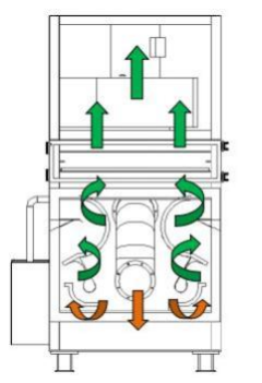
3.1 Equipment principle
When dust-laden gas is drawn into inlet chamber, airflow turns downwards and impacts water surface; larger particles fall directly into water. Fine dust passes through S-shaped narrowing channel between upper and lower impellers. Airflow velocity increases, creating water droplets and fine mist, ensuring thorough gas-liquid contact. Sudden change of airflow creates centrifugal force, throwing dust against outer wall where water mist captures them. After leaving S-channel, clean air misting chamber reduces velocity; baffle plates separate water mist, which washes dust and returns to tank. Purified gas is de-watered and exhausted by fan; sludge is discharged periodically or continuously via sludge valve.
3.2 Equipment structure
⚠️ At least 500mm should be reserved in front of the equipment to facilitate later maintenance and internal cleaning.
3.3 Liquid level control
Startup procedure: Before starting machine, close drain valve, open inlet valve and add water. When liquid level aligns with overflow port, float valve automatically closes inlet. Then close inlet valve; machine is ready to run. This ensures correct pumpless water circulation.
4. Safety instructions
4.1 Installation requirements
Open packaging, read nameplate. Power supply: three-phase 380V (50Hz), three-phase five-wire. Equipment must be reliably grounded.
Unloading personnel must be qualified. Check collector stability before unloading; use proper tools.
Maintain balance during unloading – center of gravity at air outlet (upper part). Prevent tilting or overturning.
Installation location: 1 m to 2 m from pollution source (short duct, low resistance). Reduce bends to avoid dust accumulation and water pooling.
Place on stable, vibration-free surface. Keep surrounding ventilated, dry, and protected from rain.
Installation height: generally 1.5 m – 2 m. Adjust according to site conditions to ensure fan performance.
Connecting pipes must be smooth, airtight, and without leakage to ensure effective dust capture.
After unloading, inspect and clean equipment to guarantee performance and service life.
4.2 Instruction manual (operating notes)
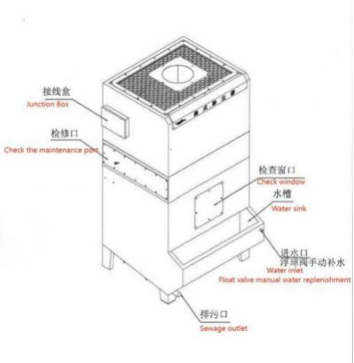
Water level must be placed at the "water level line" standard.
Right side of water tank: overflow outlet (DN20) and sewage outlet (DN40).
Water inlet (DN20) is located on rear side of voltage stabilizing box.
Please check equipment operation regularly after use.
5. Equipment maintenance
5.1 Routine maintenance
Designate a person to manage equipment and keep work records.
Operators must fully understand performance, structure, and procedures; address problems promptly.
When shutting down, after process system stops, keep dust collector and fan running unloaded for a period to remove moisture and dust.
Clean dust collection pipes after each shift; tap hoods, pipes, and bends to prevent dust accumulation.
Water level check: every 3‑5 days, keep within marked line; add water if needed.
Pipe cleaning: every 7‑15 days (depending on usage) remove dust collection pipe, check blockages and clean. First inspection at 7 days.
Deep cleaning: every 15‑30 days clean filter element, flow channel, and internal dust. For 3 kW unit, focus on rear flow channel via rear inlet.
5.2 Troubleshooting and elimination methods
| Fault characteristic | Cause of fault | Elimination methods |
|---|
| Dust collector not working | Factory voltage fluctuates (undervoltage/overvoltage)
Excessive current caused thermal overload trip | Factory internal negotiation to resolve
Check motor; may have tripped due to thermal overload |
| Abnormal running resistance | Liquid level too high/low
Process system not working | Regulate water level
Resumption of work |
| Insufficient suction | Pipes clogged or damaged
Dust accumulation
Liquid level too high
Motor wires connected in reverse | Clean or replace pipes
Timely sewage discharge
Lower water level
Swap any two of three UVW lines |
| Excessive emission concentration | Dust concentration too high
Low liquid level
Filtered water saturation | Reduce inhaled dust concentration
Raise water level
Regularly drain sewage and change water |
Note: If dust collector malfunctions or actual operating conditions differ significantly from original design, please contact our company promptly for a solution.
Author: ADV Grinding
Key Words: Deburring Machine, Deburring Solutions, Wet Dust Collector, Industrial Dust Removal, Pumpless Water Film